Monday 1 July 2019

VMware DRS Cluster


What Is a VMware DRS Cluster?
A cluster is a group of hosts connected to each other with special software that makes them elements of a single system. At least two hosts (also called nodes) must be connected to create a cluster. When hosts are added to the cluster, their resources become the cluster’s resources and are managed by the cluster.
The most common types of VMware vSphere clusters are High Availability (HA) and Distributed Resource Scheduler (DRS) clusters. HA clusters are designed to provide high availability of virtual machines and services running on them; if a host fails, they immediately restart the virtual machines on another ESXi host. DRS clusters provide the load balancing among ESXi hosts, and in today’s blog post, we are going to explore the DRS cluster system in depth.
How Does the DRS Cluster Work?
Distributed Resource scheduler (DRS) is a type of VMware vSphere cluster that provides load balancing by migrating VMs from a heavily loaded ESXi host to another host that has enough computing resources, all while the VMs are still running. This approach is used to prevent overloading of ESXi hosts. Virtual machines can have uneven workloads at different times, and if an ESXi host is overloaded, performance of all VMs running on that host is reduced. The VMware DRS cluster helps in this situation by providing automatic VM migration.
For this reason, DRS is usually used in addition to HA, combining failover with load balancing. In a case of failover, the virtual machines are restarted by the HA on other ESXi hosts and the DRS, being aware of the available computing resources, provides the recommendations for VM placement. vMotion technology is used for this live migration of virtual machines, which is transparent for users and applications.
Resource pools are used for flexible resource management of ESXi hosts in the DRS cluster. You can set processor and memory limits for each resource pool, then add virtual machines to them. For example, you could create one resource pool with high resource limits for developers’ virtual machines, a second pool with normal limits for testers’ virtual machines, and a third pool with low limits for other users. vSphere lets you create child and parent resource pools.
Resource pools of a DRS cluster
When Are DRS Clusters Used?
The DRS solution is usually used in large VMware virtual environments with uneven workloads of VMs in order to provide rational resource management. Using a combination of DRS and HA results in a high-availability cluster with load balancing. The DRS is also useful for automatic migration of VMs from an ESXi server put in maintenance mode by an administrator. This mode must be turned on for the ESXi server to perform maintenance operations such as firmware upgrades, installing security patches, ESXi updates etc. There cannot be any virtual machines running on an ESXi server entering maintenance mode.
DRS Clustering Features
Main DRS clustering features are Load Balancing, Distributed Power Management, and Affinity Rules.
Load Balancing is the feature that optimizes the utilization of computing resources (CPU and RAM). Utilization of processor and memory resources by each VM, as well as the load level of each ESXi host within the cluster, is continuously monitored. The DRS checks the resource demands of VMs and determines whether there is a better host for the VM to be placed on. If there is such host, the DRS makes a recommendation to migrate the VM in automatic or manual mode, depending on your settings. The DRS generates these recommendations every 5 minutes if they are necessary. The figure below illustrates the DRS performing VM migration for load balancing purposes.

Load balancing in a VMware DRS cluster
Distributed Power Management (DPM) is a power-saving feature that compares the capacity of cluster resources to the resources utilized by VMs within the cluster. If there are enough free resources in the cluster, then DPM recommends migrating the VMs from lightly loaded ESXi hosts and powering off those hosts. If the cluster needs more resources, wake-up packets are sent to power hosts back on. For this to function, the ESXi servers must support one of the following power management protocols: Wake-On-LAN (WOL), Hewlett-Packard Integrated Lights-Out (iLO), or Intelligent Platform Management Interface (IPMI). With the DRS cluster’s DPM, you can save up to 40% in electricity costs.
The Distributed Power Management feature of VMware Distributed Resource Scheduler cluster.
Affinity Rules allow you some control over placement of VMs on hosts. There are two types of rules that allow keeping VMs together or separated:
  • affinity or anti-affinity rules between individual VMs.
  • affinity or anti-affinity rules between groups of VMs and groups of ESXi hosts.
Let’s explore how these rules work with examples.
1. Suppose you have a database server running on one VM, a web server running on a second VM, and an application server running on a third VM. Because these servers interact with each other, three VMs would ideally be kept together on one ESXi host to prevent overloading the network. In this case, we would select the “Keep Virtual Machines Together” (affinity) option.
2. If you have an application-level cluster deployed within VMs in a DRS cluster, you may want to ensure the appropriate level of redundancy for the application-level cluster (this provides additional availability). In this case, you could create an anti-affinity rule and select the “Separate Virtual Machines” option. Similarly, you can use this approach when one VM is a main domain controller and the second is a replica of that domain controller (Active Directory level replication is used for domain controllers). If the ESXi host with the main domain controller VM fails, users can connect to the replicated domain controller VM, as long as the latter is running on a separate ESXi host.
3. An affinity rule between a VM and an ESXi host might be set, in particular, for licensing reasons. As you know, in a VMware DRS cluster, the virtual machines can migrate between hosts. Many software licensing policies – such as database software, for example – require you to buy a license for all hosts on which the software runs, even if there is only one VM running the software within the cluster. Thus, you should prevent such VM from migrating to different hosts and costing you more licenses. You can accomplish this by applying an affinity rule: the VM with database software must run only on the selected host for which you have a license.  In this case, you should select the “Virtual Machines to Hosts” option. Choose “Must Run on Host” and then input the host with the license. (Alternatively, you could select “Must Not Run on Hosts in Group” and specify all unlicensed hosts.)
You can see how to set affinity rules in the setup section below.
Requirements for Setting Up a DRS Cluster
The following requirements must be met to set up a DRS cluster:
  • CPU compatibility. The maximum compatibility of processors between ESXi hosts is required. Processors must be produced by the same vendor and belong to the same family with equivalent instructions sets. Ideally, the same processor model should be used for all ESXi hosts.
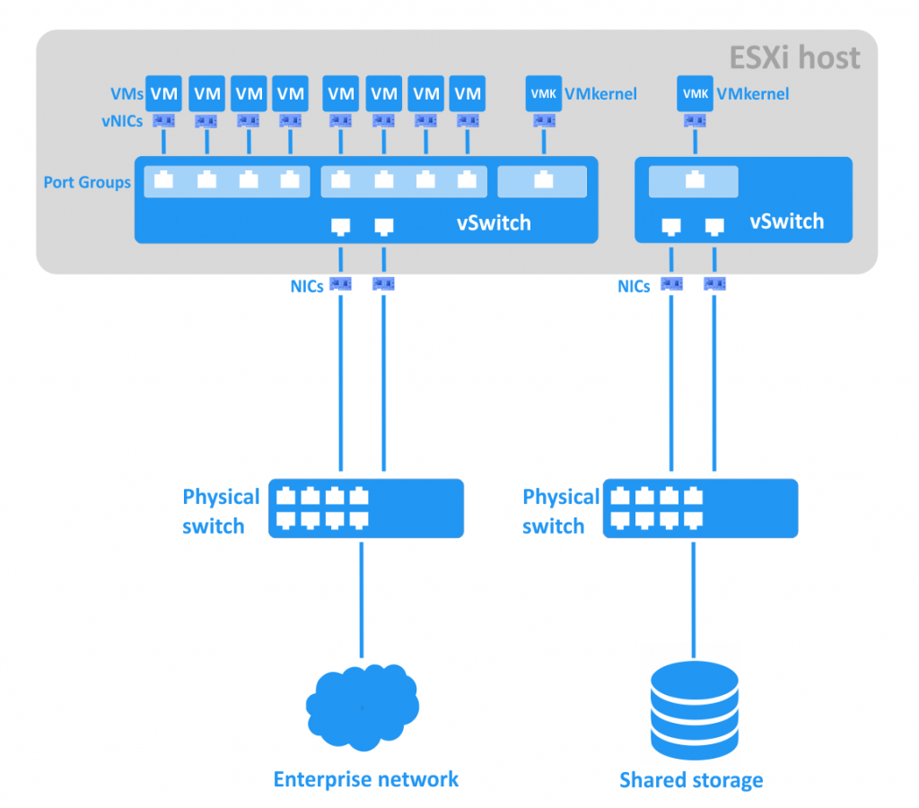
  • Shared datastore. All ESXi hosts must be connected to shared storage such as SAN (Storage Area Network) or NAS (Network Attached Storage) that can access shared VMFS volumes.
  • Network connection. All ESXi hosts must be connected to each other. Ideally, you would have a separate vMotion network, with at least 1Gbit of bandwidth, for VM migration between hosts.
  • vCenter Server must be deployed to manage and configure the cluster.
  • At least 2 ESXi servers must be installed and configured (3 or more ESXi servers are recommended).
How to Set Up the DRS Cluster
First, you need to configure the ESXi hosts, network connection, shared storage, and vCenter server. After configuring those, you can set up your DRS cluster. Log in to vCenter server with the vSphere web client. Create a datacenter in which to place your ESXi hosts: vCenter -> Datacenters -> New Datacenter. Then, select your datacenter and click Actions -> Add Host to add the ESXi hosts you need, following the recommendations of the wizard. Now you are ready to create a cluster.
In order to create a cluster, do the following:
  • Go to vCenter -> Hosts and Clusters.
  • Right-click on your datacenter and select “New Cluster”.
  • Set the name of the cluster and check the box marked “Turn on DRS”. Click “OK” to finish.
If you have already created a cluster, follow these steps:
  • Go to vCenter -> Clusters -> Your cluster name.
  • Open Manage -> Settings tab.
  • Select “vSphere DRS” and click “Edit”.
  • Check the box marked “Turn ON vSphere DRS”. Click “OK” to finish.
Now that you have created the DRS cluster, you can configure DRS automation, DPM, affinity rules, and other options.
DRS automation. In order to set up the load balancing, you need the “DRS Automation” section. Here, you can select the Automation Level (Manual, Partially Automated, or Fully Automated), as well as the Migration Threshold (values from 1 to 5, with 1 being conservative and 5 being aggressive). If you want to set up individual virtual machine automation levels, then check the appropriate box.
DRS automation settings
Power Management. You can set up DPM by selecting one of the following values: Off, Manual, or Automatic. As with the load balancing feature described above, you can select the DPM threshold values from 1 (conservative) to 5 (aggressive).
Distributed Power Management settings for the DRS cluster
Advanced Options. You can manually set the advanced options for detailed tuning of your cluster.
For example, you can set “MinImbalance 40” for computing target imbalance. The default value is 50, while 0 is the most aggressive. You can read more about this and explore all the advanced options in the VMware documentation.
Affinity Rules. In order to set up affinity and anti-affinity rules, follow these steps:
1. Go to vCenter -> Clusters -> your cluster name
2. Go to Manage -> Settings tab
3. Select “DRS Rules” and click “Add”Set a name for the rule
4. Select the rule type:
  • Keep Virtual Machines Together (affinity)
  • Separate Virtual Machines (anti-affinity)
  • Virtual Machines to Hosts (affinity or anti-affinity)
  • Affinity rules settings
5. Select VMs for the first two rule types, or VM groups, host groups and policy for the third rule type
6. Click “OK” to finish.
Resource Pools. If you would like to create a resource pool for your VMs in a cluster, do the following:
  • Go to vCenter -> Clusters -> Your cluster name.
  • Click Actions -> New Resource Pool.
  • Give the pool a name, then define limits and reservations for CPU as well as memory. Click “OK” when done.
  • Creating a new resource pool for the DRS cluster
Now you can add your virtual machines to the resource pool. Here is how you can migrate an existing VM to the resource pool:
  • Go to vCenter -> Virtual Machines.
  • Select your virtual machine.
  • Click Actions -> Migrate. The wizard window appears.
  • Select “Change Host” in the “Migration Type” section and click “Next”.
  • Select your resource pool in the “Select Destination Resource” section and click “Next”.
  • In the “Review Selections” section, click “Finish”.
After configuration, you can check the state of your newly created DRS cluster. Just go to vCenter -> Clusters -> Your cluster name and click the “Summary” tab.
Viewing the summary of a VMware DRS cluster with vSphere Web Client
The Advantages of Using DRS
The main advantage of using a VMware DRS cluster is effective resource management with load balancing. This improves the quality of services provided, while also allowing you to save power (and, thus, money) with DPM. You can control the virtual machine placement manually or automatically, which makes maintenance and support more convenient.

VMware vSphere Client

VMware vSphere Client 6.7: Should You Upgrade?

VMware vSphere is currently one of the most popular virtualization platforms, which is partly attributed to its constant development of new features and enhancing of existing functionality. Its latest release – VMware vSphere Client 6.7 – took place on April 17th, 2018 and introduced some additional improvements to both the VMware hypervisor (ESXi) and management console (vCenter Server). In this blogpost we will discuss how the vSphere functionality has changed since the previous release and what new benefits it can provide.

About VMware vSphere

VMware vSphere is not a stand-alone product that you can simply install. On the contrary, it encompasses the VMware's suite of server virtualization products, which are used to build, configure, manage, and provision virtual environments. Some of the vSphere components are listed below:
  • ESXi is a bare-metal hypervisor which is used for creating and provisioning virtual machines (VMs).
  • vCenter Server is a centralized platform which is applied for managing all ESXi servers and the VMs running on those servers from a single pane of glass.
  • vSphere Update Manager is a software product that tracks all the latest updates in vSphere and enables automated patch management for eliminating any vulnerabilities in the system.
  • vSphere Client is a Windows application which can directly connect to vCenter Server or ESXi hosts. It provides a graphical user interface (GUI) through which you can monitor and access the computing resources and VMs running in virtual environment.

Newest Features of VMware vSphere Client 6.7

VMware is determined to keep up with the newest technology trends and meet customers’ expectations. The latest release of VMware vSphere introduced multiple features which have considerably improved vSphere functionality and eliminated the issues existing in its previous versions. Let’s discuss those enhancements in detail:
  • ESXi Quick Boot allows you to rapidly reboot the ESXi server during system updates or upgrades by avoiding re-initialization of the physical server. Instead, if the OS needs to be restarted, only the ESXi host is shut down and then immediately rebooted. This feature is integrated into vSphere Update Manager and can be enabled manually during host patching. With Quick Boot, you can significantly reduce time spent on patch management and upgrading.
  • ESXi Single Reboot helps shorten the time needed to perform major system upgrades. The upgrade process previously required two reboots, but ESXi Single Reboot has cut the number of reboots from two to one. Thus, if you are working in large virtual environments hosting multiple VMs, you no longer have to worry about long downtime during system upgrades.
  • Cross-vCenter Encrypted vMotion enables secure transfer of data from one vCenter server instance to another due to the use of encryption. With this feature, you can not only move data from one data center to another, but also perform data center migrations without worrying about your data getting compromised or corrupted.
  • Trusted Platform Module (TPM) 2.0 and virtual TPM (vTPM). TPM was specifically designed to perform cryptographic operations, such as creating and storing passwords or encryption keys. VMware vSphere 6.7 provides support for TPM 2.0 because it enables one of the vSphere features – Secure Boot, which was introduced with vSphere 6.5. Secure Boot ensures that any driver or application loaded on the ESXi host can be trusted by checking whether it is cryptographically signed. Moreover, vSphere has introduced support for vTPM, which is used to protect VMs. Thus, this feature ensures a high level of security within your virtual environment.
  • VMware vCenter Server Appliance Backup Scheduler can be used for scheduling backups. The schedule can be set up to run backup jobs daily or weekly, or you can create a custom schedule based on your needs and preferences. Moreover, Backup Scheduler allows you to select the number of backups which you want to retain.
  • Enhanced vMotion Compatibility (EVC) is applied when the data is moved across data centers (on premises and the cloud). This feature allows to create and assign EVC baselines on a per VM basis, rather than on a per ESXi-host basis. Thus, you can modify all ESXi hosts in a cluster to share the same CPU features, which ensures seamless migration of workloads.
  • HTML5-based vSphere Client has replaced Flash-based vSphere Web Client. Thus, you can now enjoy the benefits of working in a simple and intuitive user interface. Thus, VMware has extended the functionality of vSphere Client, which simplifies the process of managing daily workloads and multiple vSphere components.
  • Instant Clone allows you to create a powered-on copy of a VM at a particular point in time, meaning that the clones are created in a fully operational mode and are ready for use. This feature can be accessed through API. Instant clones share a virtual disk, as well as memory, of a source VM and, therefore, require less storage space than full clones. Moreover, you do not need to power off a parent VM to create instant clones as this technology allows you to create identical copies of the running VMs. Thus, this feature ensures better use of memory, simplified patching, and seamless resource provisioning.
  • Persistent Memory is a byte-addressable form of computer memory. Persistent Memory is regarded as a type of non-volatile dual in-line memory module (NVDIMM) that allows you to operate in a storage with the following characteristics: DRAM-like latency and bandwidth, DRAM byte-level access, regular load/store CPU instructions, and DRAM-like OS memory mapping. The main benefits of vSphere Persistent Memory is that it reduces the load on infrastructure and cuts the time spent on maintenance and upgrades.
  • Scale Enhancements. VMware has increased some of the configuration maximums to provide support for even larger virtual environments than before. The following table will demonstrate how key scale metrics have changed across vSphere versions.
Maximums vSphere Version
5.5 6.0 6.5 6.7
Host per Cluster 32 64 64 64
VMs per Cluster 4000 8000 8000 8000
CPUs per Host 320 480 576 768
RAM per Host 4 TB 12 TB 12 TB 16 TB
VMs per Host 512 1024 1024 1024
vCPUs per VM 64 128 128 128
vRAM per VM 1 TB 4 TB 6 TB 6 TB
Fault Tolerance 1 vCPU 4 vCPU 4 vCPU 8 vCPU
Non-Volatile Memory per Host


1 TB
Non-volatile Memory per VM


1 TB

Should You Upgrade to VMware vSphere Client 6.7?

The latest vSphere version provides multiple benefits that can significantly improve your experience in a virtual environment. These benefits include built-in security and scalability, lifecycle management, workload optimization, improved memory utilization, accelerated patching, and enhanced app performance.
Upgrading VMware
However, before upgrading to VMware vSphere Client 6.7, you should first consider whether its new features can be used to improve your infrastructure and meet your business needs. It is probable that your infrastructure simply doesn’t require new functionality at the moment as your organization can’t derive any benefits from those enhancements. Or, there might be some compatibility issues because your software and hardware do not support vSphere 6.7. Check out the VMware Compatibility Guide to identify whether your infrastructure can support the latest version of vSphere.

VMware vSwitch

What Is VMware vSwitch?

Virtual machines connect to a network much in the same way physical ones do. The difference is that the VMs use virtual network adapters and virtual switches to establish connections with physical networks. If you have used VMs running on VMware Workstation, you may be familiar with three default virtual networks. Each of them uses a different virtual switch:
  • VMnet0 Bridged network – allows connection of a VM’s virtual network adapter to the same network as the physical host’s network adapter.
  • VMnet1 Host Only network – allows connection to a host only, by using a different subnet.
  • VMnet8 NAT network – uses a separate subnet behind the NAT, and allows connection of the VM’s virtual adapter through the NAT to the same network as the physical host’s adapter.
ESXi hosts also have virtual switches, but their settings are different. Today’s blog post explores the use of VMware virtual switches on VMware ESXi hosts for virtual machine network connections.

Definition of vSwitch

A virtual switch is a software program – a logical switching fabric that emulates a switch as a layer-2 network device. A virtual switch ensures the same functions as a regular switch, with the exception of some advanced functionalities. Namely, unlike physical switches, a virtual switch:
  • Does not learn the MAC addresses of transit traffic from the external network.
  • Does not participate in Spanning Tree protocols.
  • Cannot create a network loop for redundant network connection.
VMware’s virtual switches are called vSwitches. vSwitches are used for ensuring connections between virtual machines as well as connecting virtual and physical networks. A vSwitch uses a physical network adapter (also called NIC - Network Interface Controller) of the ESXi host for connection to the physical network. You might want to create a separate network with a vSwitch and physical NIC for performance and/or security reasons in the following cases:
  • Connecting storage, such as NAS or SAN, to ESXi hosts.
  • vMotion network for live migration of virtual machines between ESXi hosts.
  • Fault Tolerance logging network.
If a malefactor could access one of the virtual machines in one vSwitch’s network, he or she would be unable to access the shared storage connected to the separate network and vSwitch, even if they resided on the same ESXi host.
The schema below shows the network connections of VMs residing on an ESXi host, vSwitches, physical switches, and shared storage.
Virtual switches of an ESXi host
You can make a segmented network on an existing vSwitch by creating port groups for different VM groups. This approach can make it easier to manage large networks.
A Port Group is an aggregation of multiple ports for common configuration and VM connection. Each port group has unique network label. For example, in the sceenshot below, the “VM Network” created by default is a port group for guest virtual machines, while the “Management Network” is a port group for the EXSi host’s VMkernel network adapter, with which you can manage the ESXi. For storage and vMotion networks, you will need to connect a VMkernel adapter that can have a different IP address for each network. Each port group can have a VLAN ID.
A simple topology of vSwitch with two port groups.
The VLAN ID is the identifier of a VLAN (Virtual Local Area Network) that is used for VLAN tagging. VLAN IDs can be set from 1 to 4094 (the 0 and 4095 values are reserved). With VLAN, you can logically divide networks that exist in the same physical environment. VLAN is based on the IEEE 802.1q standard and operates on the second layer of the OSI model, the Protocol Data Unit (PDU) of which is frame. A special 4-byte tag is appended for Ethernet frames, enlarging them from 1518 bytes to 1522 bytes. The maximum Transmission Unit (MTU) is 1500 bytes; this represents the maximum size of encapsulated IP packets without fragmentation. Routing between IP networks is performed on the third layer of the OSI model. See the diagram below.
Connection of port groups with VLAN IDs
Each port in a vSwitch can have a Port VLAN Identifier (PVID). Ports that have PVIDs are called “tagged ports” or “trunked ports”. A trunk is a point-to-point connection between network devices that can transmit the data from multiple VLANs. Ports without PVIDs are called untagged ports – they can transmit the data of only one native VLAN. Untagged ports are typically used between switches and endpoint devices such as network adapters of user machines. The endpoint devices usually don’t know anything about VLAN tags, and they operate with normal untagged frames. (The exception is if the virtual machine has the “VMware Virtual Guest Tagging (VGT)” feature configured, in which case the tags are recognized).

Types of Virtual Switches

VMware vSwitches can be divided into two types: standard virtual switches and distributed virtual switches.
A vNetwork Standard Switch (vSwitch) is a virtual switch that can be configured on a single ESXi host. By default, this vSwitch has 120 ports. The maximum number of ports per ESXi host is 4096.
Standard vSwitch features:
Link discovery is a feature that uses Cisco Discovery Protocol (CDP) to gather and send information about connected switch ports that can be used for network troubleshooting.
Security settings allow you to set security policies:
  • Turning the Promiscuous Mode option on lets the guest virtual adapter listen to all traffic, rather than just the traffic on the adapter’s own MAC address.
  • With the MAC Address Changes option, you can allow or disallow changing the MAC address of a VM’s virtual network adapter.
  • With the Forged Transmits option, you can permit or block the sending of output frames with different MAC addresses than the one set for the VM adapter.
NIC teaming. Two or more network adapters can be united in a team and uplinked to a virtual switch. This increases bandwidth (link aggregation) and provides a passive failover in case one of the teamed adapters goes down. The Load Balancing settings allow you to specify an algorithm for traffic distribution between NICs in the team. You can set a failover order by moving network adapters (which can be in “active” or “standby” mode) up and down in the list. A standby adapter becomes active in a case of active adapter failure.
Traffic shaping limits the bandwidth of outbound traffic for each virtual network adapter connected to the vSwitch. You can set limits for average bandwidth (Kb/s), peak bandwidth (Kb/s) and burst size (KB).
The port group policies such as security, NIC teaming and traffic shaping are inherited from the vSwitch policies by default. You can override these policies by configuring them manually for port groups.
A vNetwork Distributed vSwitch (dvSwitch) is a virtual switch that includes standard vSwitch features while offering a centralized administration interface. dvSwitches can only be configured in vCenter Server. Once configured in vCenter, a dvSwitch has the same settings on all defined ESXi hosts within the datacenter, which facilitates management of large virtual infrastructures - you don’t need to set up standard vSwitches manually on each ESXi host. When using a dvSwitch, VMs keep their network states and virtual switch ports after migration between ESXi hosts. The maximum amount of ports per dvSwitch is 60,000. The dvSwitch uses the physical network adapters of the ESXi host on which the virtual machines are residing to link them with the external network. The VMware dvSwitch creates proxy switches on each ESXi host to represent the same settings. Note: an Enterprise Plus license is required to use the dvSwitch feature.
Simplified schema of a VMware Distributed vSwitch
Compared to a vSwitch, the dvSwitch provides a wider set of features:
  • Centralized network management. You can manage the dvSwitch for all defined ESXi hosts simultaneously with vCenter.
  • Traffic shaping. Unlike the standard vSwitch, a dvSwitch supports both outbound and inbound traffic shaping.
  • Port group blocking. You can disable sending and/or receiving data for port groups.
  • Port mirroring. This feature duplicates each packet from a port to a special port with a SPAN (Switch Port Analyzer) system. This can allow you to monit traffic and perform network diagnostics.
  • Per port policy. You can set specific policies for each port, not only for port groups.
  • Link Layer Discovery Protocol (LLDP) support. LLDP is a second-layer non-proprietary protocol that is useful for monitoring of multi-vendor networks.
  • Netflow support. This allows you to monitor IP traffic information on a distributed switch, which can be helpful for troubleshooting.
Now that we have explained the features of standard and distributed vSwitches, let’s discuss how to implement them.

How to Create and Configure VMware vSwitches

By default, there is one virtual switch on an ESXi host, with two port groups – VM Network and Management Network. Let’s create a new vSwitch.

Adding a Standard vSwitch

Connect to the ESXi host with vSphere Web Client and do the following:
  • Go to Networking > Virtual switches.
  • Click Add standard virtual switch.
  • Set the vSwitch Name (“vSwitch2s”, in our case) and other options as needed. Then click the Add button.
Adding a standard VMware virtual switch
Note: If you want jumbo frames enabled to reduce packet fragmentation, you can set an MTU (Maximum Transmission Unit) value of 9,000 bytes.

Adding an Uplink

Add an uplink to ensure uplink redundancy by doing the following:
  • Go to Networking > your vSwitch name > Actions > Add uplink.
  • Select two NICs.
  • You can also set other options here, such as link discovery, security, NIC teaming, and traffic shaping.
  • Click the Save button to finish.
You can edit the vSwitch settings at any time by clicking Edit settings after selecting your vSwitch under Networking > Virtual switches.
Editing the settings of standard virtual switch

Adding a Port Group

Now that you have created a vSwitch, you can create a port group. In order to do this, follow these steps:
  • Go to Networking > Port groups and click Add port group.
  • Set the name of port group and the VLAN ID (if needed).
  • Select the virtual switch on which this port group will be created.
  • You can also configure security settings here if you wish.
  • Click the Add button to finish.
Adding a port group to a standard vSwitch

Adding a VMkernel NIC

If you want to use a dedicated VM network, storage network, vMotion network, Fault Tolerance logging network, etc., you should create a VMkernel NIC for management of the relevant port group. The VMkernel networking layer handles system traffic, as well as connecting ESXi hosts with each other and with vCenter.
In order to create a VMkernel NIC, follow these steps:
  • Go to Networking > VMkernel NICs and click Add VMkernel NIC.
  • Select the port group on which you want to create the VMkernel NIC.
  • Configure the network settings and services for this VMkernel NIC as prompted.
  • Click the Save button to finish.
Adding a VMkernel NIC to a port group of a virtual switch

Adding a Distributed vSwitch

To add a dvSwitch, log into vCenter with your vSphere web client and do the following:
  • Go to vCenter > your Datacenter name.
  • Right-click on your datacenter and select New Distributed Switch. A wizard window appears.
  • Set the name and location for your dvSwitch. Click Next.
  • Select the dvSwitch version that is compatible with the ESXi hosts within your datacenter. Click Next.
  • Edit the settings. Specify the number of uplink ports, network input/output control, and the default port group. Click Next.
  • In the Ready to complete section, click Finish.
Now you can configure the dvSwitch you created. Go to Home > Networking > your Datacenter name > your dvSwitch name and select the Manage tab. The screenshot shows the features and options you can set by clicking on them.
Distributed vSwitch settings window
First, the ESXi hosts must be added to your distributed virtual switch:
  • Click Action > Add and Manage Hosts. A wizard window is launched.
  • In the Select task section, select “Add hosts” and click Next.
  • Click New host and select the ESXi host(s) you want to add. Click OK. Check the box in the bottom of the window if you want to enable template mode. Then click Next.
  • If you have enabled template mode, select a template host. The template host’s network settings will be applied to the other hosts. Click Next.
  • Select network adapter tasks by checking the appropriate boxes. You can add physical network adapters and/or VMkernel network adapters. Click Next when you are ready to proceed.
  • Add physical network adapters to the dvSwitch and assign the uplinks. Click Apply to all and then Next.
  • Manage VMkernel network adapters. In order to create a new VMkernel adapter, click New Adapter. You can then select a port group, IP address, and other settings. After completing this step, click Next.
  • You are presented with an impact analysis. Check to make sure that all dependent network services work properly, and if you are satisfied, click Next.
  • Under the Ready to complete section, review the settings you selected and click the Finish button if you are satisfied.
In order to add a new distributed port group, follow these steps:
  • Click Actions > New Distributed Port Group.
  • Set the name and location of the port group, then click Next.
  • Configure the settings of the port group. In this step, you can configure port binding, port allocation, number of ports, network resource pool, and VLAN. Click Next when you’re ready.
  • Under the Ready to complete section, review the settings you selected and click the Finish button if you are satisfied.
You now have your basic dvSwitch configuration ready. You can change the settings at any time for the purposes of conforming to changing demands.

The Advantages of Using vSwitches

Having considered how to set up VMware virtual switches, let’s summarize the advantages of using them:
  • Separation of networks with VLANs and routers, allowing you to restrict access from one network to another.
  • Improved security.
  • Flexible network management.
  • Fewer hardware network adapters needed for redundant network connection (compared to physical machines).
  • Easier migration and deployment of VMs.